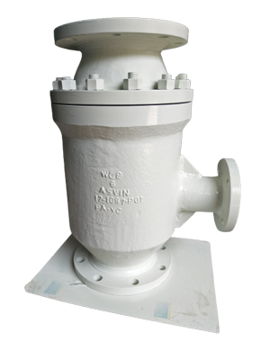
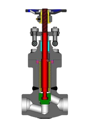
Automatic Recirculation Valves
ASVIN Automatic recirculation valve (ARC valve) is a kind of pump
protection device. It automatic protects centrifugal pump when
pump body occur cavitation damage or unstable (especially
conveying hot water at low load operation medium). Once pump
flow is lower than the preset flow, bypass can completely open to
ensure the minimum required flow pump. Even running fully closed,
namely running flow is zero, the minimum flow can also pass bypass
for Automatic Recycle. Pressure reduced through the multistage
bypass pressure reducing valve.
ASVIN Automatic recirculation valve has big bypass, and this valve is
suitable for bypass with big flow, maximum pressure differential is
4MPa, specific choice is determined by factory.
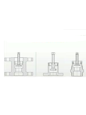
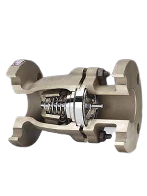
According to the difference of inductive main flow, main valve disc
check cone of automatic recirculation valve will automatically move
to a certain position. At the same time the main valve disc drive
bypass valve stem, transfer the movement of main valve disc to
bypass, through control bypass valve disc position, change bypass
throttling area, so as to control bypass flow. When main valve disc
back into valve seat closed, all flow backflow through bypass. When
mian valve disc to rise to top position, bypass is fully closed, all the
flow of pump flow to process system. This valve set four functions in
one body.

Ball Valves
ASVIN range of Ball Valves are designed for use in hazardous and
corrosive environment. All Ball Valves are preciously machined,
designer durability and maximum efficiency to provide high quality and
low cost.
Options: Full Bore - Three Piece - Turnunion
Features
- Manufacturing Standard BS 5351
- Testing Standard BS 5146
- Anti Blow Out stem
- One piece, 2 piece 3 piece and Full Bore, Reduced Bore
- End connection, screwed, socket weld, flanged and buttwelded extended pipes
- Valves with actuators can be supplied
- Valves 150 and above can be supplied with gear operation
- Valves can be supplied in Hastelloy "B" & "C" and Alloy Steel Material
- Valves with special seats are offered for high temp services and also for full vacuum, and glass filled PTFE Seats can be provided on request
- Valves can be offered with IBR Certificates
Design Standards: BS-5351/API-6D
Face To Face Dimension: ANSI B 16.10
Material of Construction
Size Range
15mm to 600 mmPressure Rating
150/300/600/900/1500/2500 class.Design
Fire safe design available.Ends
Screwed to BSP/BSPT/NPT for sizes 15 mm to 50 mm flanged to ANSI.DIN or BS standards for sizes 15 mm to 600 mm socket weld to ANSI B 16.11. for sizes 15 mm to 50 mm butt weld to ANSI B 16.25 for sizes 15 mm to 600 mm.
Accessories for Control Valves
Pneumatic
Styling, strength, compactness and simplicity of design have been combined to produce the best rotary actuator on the market today.Bray pneumatic actuators are rack and pinion, opposed-piston actuators available in two versions: double acting and spring return.
They have a maximum pressure rating of 140 psi (10 Bar) and a temperature range of -13°F (-25°C) to -200°F (95°C). Offered for the first time to the industry are the unique actual are the unique actual piston guides and rings which have a very low coefficient of friction and absorb the side thrusts of the piston. Other features include internal porting which reduces the cost of easily damaged external tubing position indicator and travel stop adjustments.
Our patented spring return unit is designed with the housing length the same size as our double acting unit, and the spring cartridges are inherently safe.
The standard spring cartridge system is available for
40, 60, 80 and 100 psi services (3, 4, 5, 6 and 7 Bar).
Electric Actuators
Bray electric actuators are powered by a rugged high-torque, integral, single phase, reversible motor.All models feature a disengage cable manual override. Included are two SPDT switches, shaft position indicator, motor overload protector and Available in NEMA 4 or NEMA 7 housings. Output torque from 275 to 48,000 Ib-ins.
Worm Gear
For manual override of pneumatic actuators. During pneumatic operation of the valve, the worm of the gear unit is disengaged. Should the valve require opening or closing in the event of power loss, manual rotation of the declutch lever will provide a camming action and engage th worm to the segmented worm the worm to the segmented worm gear.Reverse rotation of the lever will allow for disengagement of the unit. Excellent for safe handling of spring return actuators. Available for 2” - 48” (50mm-1200mm) valves.
Excess Flow Check Valves
"ASIAN Excess Flow Check Valves" are safety mechanisms. They are to
be installed in flow lines to and from pressure tanks, as near to the
tank as possible. Their purpose is to shut off the flow of fluid from the
tank in case of breakage or rupture of any flow line or fitting located
on the outlet side of the valve.
Excess Flow Check Valves are normally open valves. They are to be
positioned in the tank line or tank fitting so that high velocity of
flow outward from the tank will force the valves to the closed
position.
Each valve design is rated for one particular maximum rate
of flow. It will allow the passage of any rate of flow less than, and
up to and including, this maximum flow rate.
With an increase of
velocity of flow, the valve will remain closed as long as this
differential prevails.
It is evident that, if the valve is properly
installed and the piping and fittings are properly sized for the
installation, the valve automatically will close in case of breakage
of the line or any fitting in the flow system on the side of the valve
away from the tank unless the pressure in the tank is too low to
maintain valve-closing velocity through the broken line.
When repairs to the system are made and pressure closed in, the slight
seepage through the small orifice in the excess flow check valve
head will, in time, allow pressures to equalize on both sides of the
excess flow check valve and the excess flow check valve again will
open to flow position and will be ready for further use.
Flow lines should be as short and as free from bends and other flow
restrictions as possible. Lines and fittings should not be reduced to
smaller size than the size of the line for which the valve is intended
as indicated by the last size code letter in the valve number.
Non-Return Check Valves
Check valves are fluid control devices that restrict the flow of
media in a piping system to one direction. This broadly defined
check valve function plays different roles in various industries.
Also known as non-return valves, one-way valves, or backflow
preventers, check valves prevent flowing media from flowing back
upstream.
Often called flapper style check valves, swing check valves are a
more traditional variety.
The disc of a swing check valve is secured
to the body of the valve by a trunnion and hinge arm, without the
aid of a spring. Unlike a non-slam check valve, which opens and
closes at rates comparable to the pressure of the fluid flow, a swing
check valve opens and closes more suddenly, relying on the
installation orientation, gravity, and reversing flow to close the
valve.
Swing valves, because of their less controlled opening and closing
mechanics, are used in less sensitive applications.
They are most commonly employed in large-scale pipeline applications, such as
liquid, gas, and steam, generally only in horizontal configurations.
In particular, they’re often used in natural gas applications, as
natural gas processing generally does not require as stringent
pressure control as the oil and refining industry or in sewage and
water treatment systems.
Both non-slam check valves and swing check valves are suitable for
use in a wide range of applications.
Generally, though, non-slam
check valves are ideal for vertical runs of piping, or complex
applications that require constant and controllable pressure levels.
Alternatively, swing valves are often used in very large-volume
applications, horizontal pipe runs, and those applications in which
varying pressures and flow rates are not a concern. Due to the
precise pressures required, non-slam check valves are commonly
specified in various oil and gas, refining, and power industry
processes.

Non-Slam Check Valves
Some styles of check valves are specifically designed to allow their
disc, or flapper, to slam shut in certain conditions, such as the
reversal of fluid flow.
This sudden shutting, or slamming, creates a
wave of pressure in the liquid that reverberates throughout the
system and, depending on the precise application, can ultimately
lead to reduced process efficiency, valve damage, gasketed joint
leaks and other issues.
This inevitable - but controllable - phenomenon is commonly referred to as water hammer.
Non-slam check valves are designed specifically for use in these situations.
As their name implies, these valves close without slamming, meaning
no excess pressure spikes are created.
The disc of a non-slam check
valve has an internal spring opposing the opening fluid flow
pressure.
When the flow of a media is strong enough, the spring
compresses and the valve opens; the disc is smoothly pushed back
toward the seating surface in the valve by the spring as the flow
decreases and stops, but before flow direction reverses
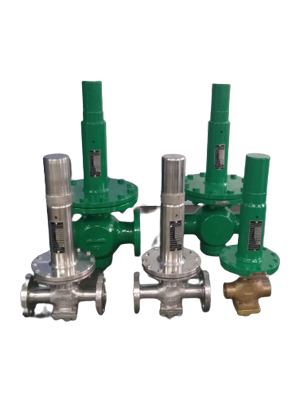
Pressure Reducing Valves
Conical Strainers strainer are temporary Strainers used mostly before
startup of a Plant.
Use perforated wire - mesh or wedge wire to trap
suspended solids from a process stream.
Conical strainers are usually
installed horizontally in a piping system.
Conical strainers are commonly used in pipelines to prevent damage of
Gauges, pumps, control valves, Flow meters and other process
equipment.
Fabricated Conical strainers from 2” to 24” (& larger sizes are
available on request) designed in accordance with ASME Section VIII Div. 1.
Conical strainer available in CS, SS304, SS316, Duplex, Super Duplex.
Conical strainers are available in both Basket type and Cone Type
Temporary Strainers.
Needle Valves

Straight needle valves are manual valves intended for continuous
throttling to achieve flow regulation.
Valves are fitted in circuits to
allow the flow to be adjusted to suit variable operating conditions.
Straight needle valves are also used in instrument impulse lines to
attenuate pressure pulsations to limit gauge reading fluctuations.
These “meter” valves are of a more robust construction. Some valves
have accurate calibration, micrometre style scales, to permit
repeatability.
Some needle valves are not recommended for isolation
purposes, so product specifications must be checked carefully.
Like globe valves there is a preferred direction of flow: fluid enters the
bottom of the seat, travels up the taper and exits from the top.
The stem of a needle valve is machined to an accurate taper and small
valves can have a very sharp point on the end.
The seat, a much longer
seat than in other valves, is machined to the same taper.
On opening, the valve creates a long narrow parallel flow passage.
As the stem is withdrawn the flow passage enlarges and reduces the flow
losses.
Straight needle valves impose high losses in a circuit and have
low C, values compared to other valve types. The nature of the flow
passage excludes solids handling, and clean fluids are essential for
acceptable component lives.
Needle value, optional with 30º poppet, V-notch, or rectangular slot.
The form of the throttle opening influences the fineness of the flow
setting, which is dependent on the pressure and viscosity.
The needle is made of stainless steel and corresponds to a ring gap in the valve
body.
The body can be steel or brass as well as for pipe line or for panel mounting.
Manifolds
Valve and 5 Valve Manifold are ideal for applications in differential pressure instruments such as differential pressure transmitters, differential pressure switches, differential pressure gauges, etc.
3 Valve Manifold, the most commonly used manifolds, could be provided with test ports on the process side and drain ports on the instrument side for draining of the process and instrument lines respectively.
Valve Manifold is suitable for applications with differential pressure instruments where drain valves are required on the instrument side.
Further, they are used for flushing of the system and for prevention of loss of expensive fluid in the impulses.
"Virgin" makes Manifold Valves which are installed to measure, control, isolate, equalise, calibrate, drain, vent or differentiate the pressure of liquids & gases.
We offer 2, 3, 5 valve manifold configuring remote mounting (pipe to pipe), direct mounting (pipe to flange T type & flange to flange H type) or panel mounting on to gauges, pressure switches or DP transmitters having 54 mm centre .
Two Valve Manifolds
Two Valve Manifold combines isolating, calibrating and venting functions in a single neat unit and is ideal for use on Pressure Gauges, Pressure Switches, Pressure Transmitters, Pressure Controllers and other Pressure Sensitive instruments.Consequently, using Two Valve Manifold, gives a saving in materials and labour as well as increasing reliability by reducing the number of leak prone joints.
Each unit is tested at 3,000 PSIG hydraulic at ambient temperature. Material of Construction :- Carbon Steel Plated and Stainless Steel.
Resulting in Lower installation Cost.
Available in carbon steel and stainless steel in following types.
Five Way
Direct mounting 'H' type manifolds is ideal for stacked assembly between the instrument and the flange process connection.Co-planar manifolds are designed for direct mounting on to the instrument which help eliminates the adapter plate.
‘T’ type manifolds are designed for direct mounting on the instrument and are connected with screwed process connections.
Remote Mounted from the transmitter Manifolds are tested to 400 kg. / CM2
Hydraulic pressure and for seat at 80 PSIG Pneumatic.
Material of Construction
Carbon Steel and Stainless Steel
end connection /2" NPTF or as per specifications
Five Valves Manifolds can be supplied
Direct Mounted on D/P transmitter in "T" and "H" type

Bellow Seal Valves
"ASIAN Industrial Valves And Instruments" manufactures ASVIN
Bellows Seal Valves include a formed bellows welded to the stem on
one side and to the bottom of the bonnet at its bottom end, creating a
tight seal.
Bellows are available in many materials for most corrosive
chemical applications.
In applications where total containment of toxic media is mandatory,
ASVIN Bellows Seal Valves carry a maintenance-free guarantee of
5,000 cycles, and a higher cycle life of 10,000 cycles is available on
request.
The valve line is offered in stainless steel 316L as the basic material
configuration; however, for severe service and corrosive applications,
exotic materials like duplex, super duplex, Hastalloy-C22 and Titanium
are also available.
ASVIN Bellows Seal Globe Valves have been reliably in service in
nuclear, power and chemical plants for more than 35 years.
Differences between conventional globe valves and bellow seal globe
valves
ASVIN Bellows Seal Globe Valve has superior sealing performance and is
more efficient to guarantee the security of pipelines with hazardous
media.
The conventional globe valve is sealed by packing and has the valve
stem not in tight contact with packing, causing high leak rates under
low temperatures.
The Bellow Globe Valve, in general, is used for pipelines of permeable
media such as ammonia since the pipeline will leak only if bellows in
seal globe valve are broken.
NDT Testing
Forgings shall be ultrasonically examined to rule out the presence of defects as per ASME B 16.34.Lip seal welds and hard facing deposit shall be subjected to DP Test as per ASTM E 165 and the acceptance criteria shall be as per ANSI B 16.34.
Flush Bottom Valves
A flush tank valve is used to drain tanks completely in those situations
where it is not feasible to shape the tank bottom to include a gravity
drain point.
Most tanks can have a sloped bottom so that all
sludge/sediment and product can be drained.
Tanks of this type have
dead volumes which cannot be stirred and product cannot be
circulated.
These operating restrictions make this style of tank
construction unsuitable for hygienic and biotechnology applications.
Equipment must be designed to allow all product to circulate freely
and pockets, where the consistency may vary from the bulk, must be
eliminated.
Flush tank valves are designed to be fabricated into tori
spherical dished ends or circular shells.
The complete contents of the
tank can be drained without inhibiting the internal flow patterns.
The valve body can be flanged to bolt to a facing fabricated into the
tank.
Alternatively, the valve body can be shaped and weld prepared,
or weld prepped, for butt welding into the shell.
The most popular
valve types are piston type sample valves.
Care must be taken
because of the very close clearances between the piston and the body.
The valve has an extremely poor tolerance to pipe strain and imposed
forces and moments and so the design of the outlet pipe is critical.
The standard valve manufactured in AISI 316L to ASME VIII Division 1 requirements. Full material traceability is maintained.
The valve body
is designed for direct fabrication into the tank bottom.
Sizes cover
DN15 to DN100 outlets.

Diaphragm Valves
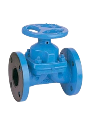
ASVIN Diaphragm Valves are designed and manufactured according to
BS 5156.
They are extensively used in water treatment plants,
fertilizer & petrochemical industries, chemical process units, refineries
and power plants.
They are suitable for positive pressure and high
vacuum applications.
Due to wide range of material options, it is
suitable to handle almost all applications within its pressure-
temperature limitations.
Total wet area and working parts are isolated from the working media
by suitable lining with various qualities of Rubber, PTFE/PFE etc.
ensures handling of highly corrosive fluids in efficient and safer
manner.
The diaphragm valve is different from all the valves previously
described because the bonnet and the stem are always completely
isolated from the product.
A diaphragm valve is almost equivalent to a
bellows sealed linear valve.
The diaphragm fulfils two functions.
Firstly, it separates the inlet from the outlet when the valve is closed
and secondly it separates the operating mechanism from the product.
The diaphragm forms a part of the pressure containment.
The diaphragm is clamped between the body and the bonnet.
Bolted bonnets are standard.
No packing box is required.
The bonnet has an
inside rising screw.
Which can have a sealed lubrication reservoir.
A shield on the handwheel is sealed by a lip seal to prevent ingress of
moisture or dust into the thread area.
The Operating mechanism is sealed both ways for long life.
Valve maintenance is easy once the line is depressurized and all parts can be removed from under the bonnet.
Valve shut-off capabilities are excellent because of the elastomer diaphragm.
Solids handling is quite good, with 15% maximum recommended concentration.
Diaphragm valves are a sensible choice
for hazardous fluids because there is no packing box to worry about.
Routine diaphragm maintenance will ensure almost total containment
and diaphragm life can be optimized by the fitting of limit stops to the
actuator.
Over-tightening is eliminated thus reducing stresses in the
elastomer.
The Precise level of containment is dependent upon the fluid.
Elastomers are permeable; Although permeation through a
diaphragm should be considerably less than the leakage through any
packing box.
Diaphragm valves are used on hydrogen services, and
containment must be good.
The diaphragm is the main limiting restriction on operational parameters.
To widen the range as much as possible a broad selection
of materials is used.
Materials are also combined to improve
flexibility and chemical resistance.
Maintenance of these Valves are made very simple.
By dismantling the
Bonnet from the Body, the entire Trim Assembly can be taken out for
maintenance and the Body remains in the Pipeline.
Thus, the design
permits online maintenance and saves time and energy.
It has linear
flow characteristics, which makes it well suited to throttling or
modulating duties.
On/off and control automation is provided with
Pneumatic Actuators or Cylinders.
Diaphragm Valves are available in varied material like Cast Iron, S.G.
Iron, Cast Carbon Steel, Stainless Steel of all grades, High Alloy Steels
like Ally-20, CD4MCu., Hastelloy etc.
Manufacturing range starts from
15NB through 200NB and pressure rating in ANSI 125/150#.
Our Products
- Safety Valve
- Relief Valve
- Safety Relief Valve
- Thermal Relief Valve
- Conventional Safety Relief Valve
- Balanced Safety Relief Valve
- Balanced Bellows Safety Valve
- Sentinal Relief Valves
- Pilot Operated Safety Relief Valves
- Rupture Disc
- Tubular Level Indicator
- Reflex Level Indicators
- Transparent Level Indicators
- Magnetic Level Indicators
- Bi-Colour Level Indicators
- Remote IGEMA Level Indicators
- Fullview Glasses
- Ball Flow Indicators
- Double Window Plain
- Double Window Drip
- Double Window Flapper
- Double Window Rotating Wheel
- OPA - Orifice Plate Assemblies
- Restriction Orifice Plate
- Integral Orifice Plate Assembly
- Flow Nozzles
- Flow Venturi
- Pitot Tube
- T Type Strainers
- Y Type Strainers
- Basket Strainers
- Duplex Strainers
- Conical / Temporary Strainers
- Magnetic Strainers
 ASVIN
ASVIN