Pipe Line Strainers
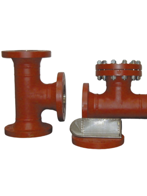
T Type Strainers
T- strainers are a custom fabricated compound strainer designed to
remove foreign particles from pipeline. Tee strainers are used where a
compact accessible strainer is needed for protection of valves.
Y Type Strainers
Y Strainers are used in application where the number of solids to be
removed is small, and where frequent clean - out is not required. A Y-
Strainer has the advantage of being able to be installed in either a
horizontal or vertical position. However, in both cases, the screening
element or "leg" must be on the "downside" of the strainer body so that
entrapped solids can be properly collected and held for disposal. A
blow down plug on the drain port will allow clean-out without removal
of the screen, and without interrupting the process flow.
Basket Strainers
Basket Strainers is in the form of a basket. With a lifting handle, all
particulate retained by the screen can be easily removed from top for
disposal. They are intended for applications where large amounts of
solids particulate are expected and where the clean out will be
frequent.


Duplex Strainers
Duplex Strainers are designed for applications where flow cannot be
shut down to service the strainer screen. Changeover is accomplished
by use of control valves.
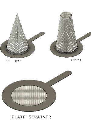
Conical / Temporary Strainers
Conical Strainers strainer are temporary Strainers used mostly before
startup of a Plant. Use perforated wire – mesh or wedge wire to trap
suspended solids from a process stream. Conical strainers are usually
installed horizontally in a piping system.
Conical strainers are commonly used in pipelines to prevent damage of
Gauges, pumps, control valves, Flow meters and other process
equipment.
Fabricated Conical strainers from 2” to 24” (& larger sizes are
available on request)
Designed in accordance with ASME Section VIII Div. 1.
Conical strainer available in CS, SS304, SS316, Duplex, Super Duplex.
Conical strainers are available in both Basket type and Cone Type
Temporary Strainers.
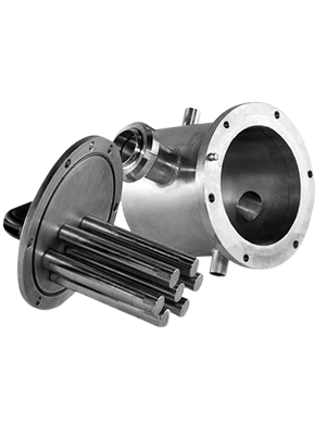
Magnetic Strainers
The purpose of a strainer is to remove larger, unwanted suspended particles from a liquid, primarily to protect downstream equipment, like pumps, from damage. They come in a variety of shapes and sizes, depending on the application, but one feature is essential, strainers are designed for easy removal and cleaning.
ASVIN basket or screen can be mesh lined to trap tiny particles in the fluid being strained. However, there are fluids that may contain microscopic metallic filings. The finest mesh will not catch these particles. This can be a problem in applications with parts that have metal to metal contact.
An effective solution to the problem of excessive and premature wear of pump seals, wear rings, bearings, gears, etc., is a magnetic screen assembly. A standard strainer basket or screen is fitted with magnets which are removable for cleaning. They are arranged to create a magnetic field around the interior of the screen or basket. The magnets attract the fine ferrous particles which would pass through the mesh and could damage the downstream equipment.
Magnets can be incorporated into most types of strainers, including y-type, basket, and temporary cone strainers.
Moisture Separators
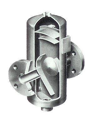
Separators are widely used in the chemical and process industries
where large volumes of liquid must be separated from gases. They
also may be used as a flash or surge tank, or as a scrubber or
demister ahead of steam turbines.
Removal of Moisture becomes essential from gases and Steam as it
cause of two-phase flow, water hammer, damage to equipment, as
well as it affects heat transfer, total heat carrying capacity of the fluid
in case of steam.
For effective separation of moisture from Steam, Air and other gases,
is the uniquely designed Baffle type of separator. In this separator the
incoming fluid hit the baffle and the changing contour and resulting in
expanding of volume, moisture gets deposited on the cool Baffle plates
to be drained by the natural inclined inner profile of the separator,
whereas the Steam / gas gets around the Baffle and out sans moisture,
ensuring 95% efficiency, and longer life of equipment.
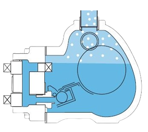
* The wet steam entered to the separation unit consist of various
baffle plates through inlet valve and it strikes baffle plate causes
change in directional flow.
* Due to large cross-sectional area, steam experience a sudden
enlargement of volume which reduces the drop in velocity.
* Therefore, the heavier water particles get deposited on baffle
plates and steam flows around the baffle.
* When the steam impinges on the baffles inside the separator
body water particles are separated from the steam flow-path due
to change in the momentum.
* The water is collected at the bottom of the separator and can be
drained off through the trap assembly fitted at the bottom of the
separator after measuring the water level through level sensor.
* Instead of depending on manual draining of the condensate water
from the collection chamber, the draining can be automated by
installing an appropriate level sensor, This sensor can be side
mounted in the water chamber as a high level detector and the
switched output can be used to control solenoid valves to drain the
water from the chamber effectively.
Steam Traps
There are several types of steam traps. The general identification for Steam trap: “TD” for thermodynamic, “TS” for thermostatic, “FT” for float + thermostatic and “IB” for inverted bucket. Thermodynamic traps have a disk situated on a central orifice. As condensate pressure builds, it lifts the disk, passes through the orifice at the center of the disk and exits through smaller orifices surrounding the disk. Flash steam builds up pressure on top of the disk and closes the orifice. Condensate is discharged intermittently.
Thermostatic traps operate on the difference in temperature between steam and condensate. As condensate cools, the volume of an enclosed bellows decreases and the discharge valve opens. Thermostatic traps always cause some condensate to remain in the system. Condensate is discharged continuously.
In Float and Thermostatic traps, condensate is discharged when the rising level of condensate lifts a float attached to a level. A thermostatically operated vent discharges air from the top of the trap. Float and Thermostatic Traps have superior gas removal characteristics. Condensate is discharged continuously.
In inverted bucket traps, steam is contained within an inverted bucket floating in condensate. As the level of condensate rises, it is discharged. Inverted bucket traps require water within the bucket, called the prime, to operate. This trap is good for distribution systems. Condensate is discharged intermittently.

Air Traps
Air Traps Remove condensate from compressed air. In today's world of
automation, compressed air is used in many industries including high-
precision machinery and instrumentation. After air is compressed, it is
cooled by an after-cooler or in a receiver tank, where condensate is
formed from water droplets in the air.
This condensate also occurs in compressed air distribution piping,
leading to rust and fluctuation in high-precision machinery, as well as
causing a reduction in product quality.
ASVIN air traps protect your equipment and products by discharging
condensate automatically.
PRDS
Pressure Reduction
cum De-Superheating Station

Types Of Pressure Temperature Reduction Units
- PRS Station
In which pressure reduction is done, is termed "Pressure Reduction Station" - DSH Station
In which temperature reduction is done, is termed "De-Superheating Station" - PRDS Station
Both units combined, termed Pressure "Reduction cum De-Superheating Station"
Pressure Reduction Station - PRS
The steam inlet pressure gauge and dial thermometer indicate the pressure and temperature respectively of the inlet steam. The Pressure Reducing Valve (PRV) reduces the pressure of the steam. The steam inlet isolation valve along with the outlet isolation valve is used to isolate the Pressure Reducing Valve, whenever maintenance of the PRV is to be carried out.The pressure transmitter senses the outlet steam pressure and gives a proportional current signal as output to the PID controller. The PID controller then compares the measured value with a set point, The safety valve opens and relieves excess pressure when steam pressure goes above set value.
- All Piping / SRV / PRV are precisely Sized with Sizing Selection Programme for Accurate Controlled Performance.
- Complete PRS is in house Fabricated with high skill IBR approved welder with seamless pipes, fittings and flanges with bypass line dully assembled and finally tested and certified by TPI, if required.
- Hydro Testing of PRS and Final Pressure setting is done with air before dispatch.It is Recommend to Provide External Balance Pipe when the Reduced Pressure is Below 55% of the Inlet Pressure
De-Superheating Station - DSH
De-superheating systems are designed to reduce the temperature of superheated steam close to that of saturation. The steam temperature is reduced close to saturation by injecting water into high velocity steam by controlled water flow through water control valve.The spray water enters the DSH station. The water strainer at the inlet prevents entry of foreign particles into the water control valve & de-superheater spray nozzles. The water inlet pressure gauge indicates the pressure of the spray water. The water flow control valve regulates the quantity of the spray water going into the spray nozzles, depending on the steam load. The temperature transmitter senses the outlet steam temperature and gives a proportional current signal as output to the PID controller. The PID controller then compares the measured value with a set point.
Reduction cum De-Superheating Station - PRDS
ASVIN can supply Pressure Reducing and de-superheating stations for whichever application regardless its criticality and dimension.- Minimum sizes available: 15 NB to higher size as per design requirement
- Available pressure rating:
- Class 150-600 Lbs (normally flanged ends)
- Class 900-2500 Lbs (normally BW ends)
- All stations are engineered and factory assembled
- Stations are mostly supplied with ‘Combined PRDS’ Valves which provide the advantage of pressure reduction and temperature control in a single unit
- The water flow Control Valve and waterline are offered with the steam line, which ensures correct design and matching of pressure and temperature control stations
- The entire assembly is hydro tested
- Stations are available in various sizes from 25 NB up to 1500 NB or larger
Pipe materials
- A106 Gr.B with flanges A105/A515 for temp. Up to 427°C
- A335 P11 with flanges A182 F11 for temp. above 427°C and below 493°C
- A335 P22 with flanges A182 F22 for temp. above 493°C
Our Products
- Safety Valve
- Relief Valve
- Safety Relief Valve
- Thermal Relief Valve
- Conventional Safety Relief Valve
- Balanced Safety Relief Valve
- Balanced Bellows Safety Valve
- Sentinal Relief Valves
- Pilot Operated Safety Relief Valves
- Rupture Disc
- Tubular Level Indicator
- Reflex Level Indicators
- Transparent Level Indicators
- Magnetic Level Indicators
- Bi-Colour Level Indicators
- Remote IGEMA Level Indicators
- Fullview Glasses
- Ball Flow Indicators
- Double Window Plain
- Double Window Drip
- Double Window Flapper
- Double Window Rotating Wheel
- OPA - Orifice Plate Assemblies
- Restriction Orifice Plate
- Integral Orifice Plate Assembly
- Flow Nozzles
- Flow Venturi
- Pitot Tube
- T Type Strainers
- Y Type Strainers
- Basket Strainers
- Duplex Strainers
- Conical / Temporary Strainers
- Magnetic Strainers
 ASVIN
ASVIN