Level Indicating Gauge
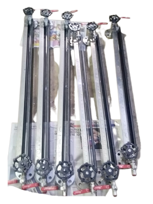
Tubular Level Indicator
Asian Industrial Valves and Instruments are the leading manufacturer
of Tubular Type Level Indicator in India. ASVIN make High accuracy
Tubular Type Level Indicator / Gauges.
ASVIN make Gauges for direct reading in atmospheric or pressurized
tank application. These indicators eliminate trouble giving threaded
joints of conventional gauge glass cock as hazardous damage
surrounding equipment & also endanger human life.
Specification
- Protected by Box Section made out of 2 mm thick S.S. channel
- We are using 100% PTFE rope as packing to ensure positive leak tightness for full vacuum as well as 6 Kg / Cm service pressure
- Tubular Level Indicator is light in weight
- It is available in single length of 2000 mm C/C Distance. We can extend the length by coupling 2 or more through coupler
- We are providing Air Vent Plug at top & drain plug at bottom
- It Eliminates trouble giving threaded joints of Conventional Gauge Glass Cock as hazardous Chemicals Start leaking
- Glass Tube (Borosilicate Boiler Quality) is fully Protected
- The connection provided will be Flanged / Screwed
Reflex Level Indicators
Reflex level gauges working principle is based on the light refraction
and reflection laws.
Reflex level gauges use glasses having the face fitted towards the
chamber shaped to have prismatic grooves with section angle of 90°.
When in operation, the chamber is filled with liquid in the lower zone
and gases or vapors in the upper zone; the liquid level is distinguished
by different brightness of the glass in the liquid and in the gas/vapor
zone. The reflex level gauges do not need a specific illumination: the
day environmental light is enough. Only during the night an artificial
light must be provided.
The different brightness in the two zones is obtained as explained
below:
Given the construction, most of the environmental light rays incident
on the external face of the glass are quite perpendicular to said face
and, therefore, not deviated by the glass. These rays reach the
glass/liquid interface with an inclination of approx. 45°. The critical
angle glass/liquid is always superior to 45°. Therefore, the ray’s
incident within the critical angle (practically the totality) are refracted
within the liquid and, since the internal walls of the gauge chamber
are not reflecting, the rays cannot be seen from the outside. In fact,
the zone will appear dark, nearly black, to the observer.
As for the liquid zone, the light rays reach the glass/gas-vapor
interface with an angle around 45°. Since this angle is greater than
glass/gas-vapor critical angle, the rays are not refracted, but totally
reflected making 90° turn, thus reaching the nearest glass/gas-vapor
interface again with angle of 45°. For same reason they will be
reflected and turned by 90°
Transparent Level Indicators
- When the separation level between two liquids has to be read
(interface) - When, besides the level indication, observation of the liquid color is required
- When the process fluid is high pressure water/steam
(since in this case the glass must be protected from the chemical attack of the boiler basic water by using mica shields) - When the process fluid is such that can corrode the glass
(e.g., high temperature alkaline solutions or hydrofluoric acid)
since mica shields or Poly trifluoro chloroethylene shields must be used to protect the glass.

Magnetic Level Indicators
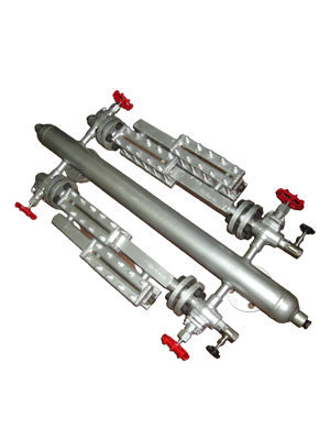
The Magnetic Level Gauge is the instrument to read a level indication
in whatever plant or operating conditions giving free maintenance,
preventive security against leakage, environmental safety, sure and
trouble-free application with chemically aggressive, pollutant, harmful
or poisonous, inflammable or explosive, optically similar fluid
interface.
Our very wide range of Magnetic Level Gauges allows to have the
proper instrument for any kind of plant or specific purpose. Our world
patented system includes a float able to float both in high density fluid
or in low density fluid up to 0.4 specific gravity. But more! You can
have low specific gravity and high temperature and pressure together
(i.e. water/steam of H.P. vessels). Well! We manufacture a float able
to float and to resist with external pressure of 210 bar at 370 ºC!
Design
In a vertical chamber (tube of suitable diameter connected by stub ends to the vessel) there is a float containing a permanent magnet - fixed by means of special patented device that permit to the magnet a 360º rotation- placed exactly on liquid level line.Magnetic action of permanent magnet in the float generates rotation of a set of small permanent magnets enclosed in small cylinders - contained in indicating scale- which cylinders, having different colours in the North and South pole, can rotate on their horizontal axis. So the scale appears of one colour (i.e. white) over chamber area taken by gas and of another colour (i.e. red) over chamber area taken up by liquid phase.
The chambers of the Magnetic Level Gauge are dimensioned according to ASME B31.1 and B31.3.
The chamber is connected to vessel with flanged, threaded or welded ends. Usually, between the instrument and its connecting ends valves are fitted to consent shut-off piping and to disassemble the level gauge without emptying the vessel or shutting off the plant. Drain valves can also be fitted on the top and bottom of level gauge.
Bi-Colour Level Indicators
Left drawing shows a typical Bicolor Glass Level Gauge, used for
measurement of water level in high pressure boiler steam drums. This
instrument consists of a stainless-steel body having trapezoid cross
section and machined to have a longitudinal chamber and front holes
uniformly distributed on the two not parallel faces.
On each hole a special high temperature resistant aluminum silicate
transparent cylindrical glass is tightly pressed between a metallic
cover and the body by means of bolts and nuts. A mica shield protect
the glass from the corrosive attack of the boiler basic water.
Belleville washers fitted between cover plates and glasses provide
compensation of their different thermal expansion, giving guarantee of
tightness at any operating condition.
The chamber is connected to vessel with cross fittings and flanged,
threaded or welded ends.
For severe conditions (over 8MPa - 1116 psi water/steam pressure)
water column and expansion joint are recommended.
Each Bicolor glass level gauge shall be fitted with top, bottom and
drain shut-off valve. Automatic shut-off ball check can be supplied.
A special back illuminator (suitable also explosion proof) gives a sharp
level reading by means of the contrast between bright color: green in
lower part (liquid) and red in upper part (steam) of level gauge.
Bicolor level gauges can be equipped with long glasses instead of
cylindrical glasses, like Transparent Level Gauge
Nevertheless we do not recommend bicolor long glass level gauges for
steam drums over 10 MPa (1450 psi).
When in operation, bicolor level gauge shows to the observer port
holes lighted green in the water zone and port holes lighted red in the
steam zone. In case of long glass gauge, the window appears part
green and part red.
This result is obtained exploiting the following optical principle:
different colors (in this case: red and green) have a different index of
refraction when passing obliquely through different media (in this
case: glass, water and steam).


Remote IGEMA Level Indicators
There are different types of remote water level indicators. Their
purpose is to bring the water level reading to some convenient position
in the engine or boiler room where it can be distinctly seen. These
indicators when fitted are normally in addition to the normal statutory
requirements for water gauge fittings for boilers.
ASVIN highly efficient remote water-level indicator, liquid level
indicators detect the water-level fluctuations in the boiler drum.
These liquid level indicators are very delicately designed to provide
flawless indications. Our highly accurate remote level indicators help
to keep a track on the displacement of the water levels in the boiler.
When the water levels in the boiler rise, the increasing water column
presses the red indicating liquid (sealing liquid) from the first phase
into second phase and then indicates in the Inspection glass of the
indicator. The best quality Red Indication liquids are only used by us.
These Remote level indicators red indication liquid have long life and
provide accurate indication. The water displaced from Phase one flows
from the condenser into Phase three and then into the boiler. If the
water level in the drum falls, then the indicating liquid in phase three
in the inspection glass, falls correspondingly. The water vapor
formation in the condenser takes place when the water level in phase
three is constantly filled up.
ASVIN Remote Boiler Level Indicator is suitable for knowing Level of
Water in Boiler Drum at Operating Floor Level. A Transparent type
Level Gauge with Illuminator at back side is fitted at Operating Floor
Level with upper side connected to Steam Side of Boiler Drum through
Front Dirt Trap and Condensation Pot and Lower Side connected to
water side of Boiler Drum through Back Dirt Trap and Bottom Dirt
Separator. Level of Red Liquid (does not mix with condensate water
and is heavier than water – Specific Gravity 1.6 approximately) inside
the transparent Level Gauge indicates the level of water in Boiler
Drum. The Condensation Pot, with a Barrier inside ensures a constant
head of water on front side of Level Gauge and applies pressure = P + h
+ h1 (Refer Fig.) where P is the Steam Pressure inside Boiler. Pressure
applied to Back side of Level Gauge is P + h + h2 . As h1 is constant,
the level of Red Liquid is proportional to h2 (Red Liquid Level is Lower
when Boiler Drum water Level is Lower and Vice versa).
Calibration Column
ASVIN calibration columns (also known as calibration cylinders) provide a simple method for determining pump capacity using graduation in millilitres/minute and Gallons/hour.
High-contrast blue or red lettering enhances readability in all light conditions, and all Indicating scales have a protective lamination layer to protect against chemical attack.
Calibration columns are available in borosilicate glass or with PVC construction:
For non-corrosive or mild chemicals, PVC calibration columns are an economical choice.
When not in use, the Calibration Column should be drained completely.
Should ensure portions of the chemical line never involve two valves shut with a slug of un-vented chemical between the valves.

Float & Chord Level Indicators

With a view to cater to the varied needs of our valuable clients, we
are engaged in manufacturing, exporting and supplying premium
quality Float & Cord Level Indicators that are widely used in various
storage tanks. Our professionals manufacture these products as per
the set industry standards using finest quality raw material. In order
to meet the varied requirements of our clients, these indicators are
available in various specifications. We assure our clients the on-time
delivery of these Float & Cord Level Indicators at rock-bottom
prices.
Features
- Robust construction
- Durability
- Low maintenance
- Trouble-free performance
The floats designed by us, are also get custom designed as per specific requirements of the customers.
- Perfectly Aligned guide wire, pulley and scale
- Float available of various desired designs and materials as per applications
- Perfect option for outdoor installations. Cast Aluminium Pulley Housing
- Spring Tensioning assembly for Guide wires
- For all kinds of Storage Tanks
Sight Glasses
A sight flow indicator is used in process pipelines to observe the flow of liquid,
powder or gas. It is comprised of a body with one or more viewing windows, usually with gaskets, and a way
to mount the indicator to the pipeline. It is installed in a pipe to provide a visual means of
verifying flow for direction and approximate rate of the process media. Through the sight flow indicator,
operators can easily observe the colour, clarity and flow of the medium passing through the window.
Fullview Glasses
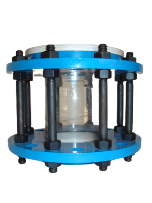
Full View Indicator also called 360° view flow indicator, cylindrical- or
tube-style flow indicator, this type of flow indicator passes fluid
through a glass cylinder that is visible from all angles. This allows
ample ambient light to illuminate the flow. It is ideal for the
observation of process fluid for clarity, colour, foam, and other
conditions, and for the presence of moisture. It is not appropriate for
high temperatures or high pressures.
Ball Flow Indicators
Flow moves a ball from the bottom of the indicator housing to a position at the top of the sight window. The ball is visible through the window so that flow may be observed easily at a glance. The suspension of the ball by the fluid indicates the presence of flow. Because gravity returns the ball to its rest position, this style of indicator must be applied in vertical pipes with upward flow. Generally this is used with slow moving fluids or gases, and not with high-rate or turbulent flows.
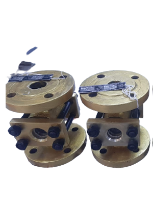
Double Window Plain
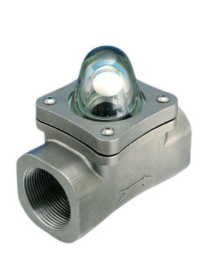
This type of flow indicator has two opposing windows so that an
operator can see the intervening flow of fluid lighted from behind,
either by ambient light or with an attached luminaire. Unlike 360-
degree full-view flow indicators, this design is suited for ANSI pressure
classes, high temperature, and harsh fluid applications
Double Window Drip
Drip indicators may be models designed for drip observation or
conventional flow indicators installed with a drip tube. Drips and low-
volume intermittent flows may be observed in applications such as
distillation. Because gravity is utilized, drip indicators are normally
applied in vertical pipes with a downward flow.

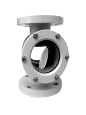
Double Window Flapper
Flow indicators may be fitted with a hinged flapper or flag visible
through the sight glass. The flapper is deflected toward the flow
direction. Because the position of the flapper changes in relationship
to the force of flow, it provides operators with an approximate gauge
of flow.
Double Window Rotating Wheel
Flow indicators may be fitted with rotors or impellers that are turned by the flow of liquid or gas. The rotors are mounted in the window view so operators can observe the direction and approximate speed of flow. This is particularly useful for clear gases and fluids, though the rotor is visible with dark fluids as well.

Our Products
- Safety Valve
- Relief Valve
- Safety Relief Valve
- Thermal Relief Valve
- Conventional Safety Relief Valve
- Balanced Safety Relief Valve
- Balanced Bellows Safety Valve
- Sentinal Relief Valves
- Pilot Operated Safety Relief Valves
- Rupture Disc
- Tubular Level Indicator
- Reflex Level Indicators
- Transparent Level Indicators
- Magnetic Level Indicators
- Bi-Colour Level Indicators
- Remote IGEMA Level Indicators
- Fullview Glasses
- Ball Flow Indicators
- Double Window Plain
- Double Window Drip
- Double Window Flapper
- Double Window Rotating Wheel
- OPA - Orifice Plate Assemblies
- Restriction Orifice Plate
- Integral Orifice Plate Assembly
- Flow Nozzles
- Flow Venturi
- Pitot Tube
- T Type Strainers
- Y Type Strainers
- Basket Strainers
- Duplex Strainers
- Conical / Temporary Strainers
- Magnetic Strainers
 ASVIN
ASVIN