Flow Elements
Flow Elements are most commonly used primary elements for flow measurement in pipe line based on "Differential Pressure" created. When the velocity increases, the pressure decreases and vice versa.
Flow elements are Designed to International Standards
viz. - ISA RP 3.2, ASME MFC-3M, ASME 19.5, ISO 5167/BS1042; R.W. MILLER and L.K. SPINK etc.,
There are three methods of placing the taps. The coefficient of the meter depends upon the position of taps.
- Orifice Plates
(corner tap, Flange tap and D & D/2 tap) - The Venturi
- The Flow nozzle
OPA
Orifice Plate Assemblies
The Orifice Plate Assembly consists of a flat orifice plate with a
circular hole drilled in it. There is a pressure tap upstream from the
orifice plate and another just downstream.
The common Orifice Plates used are:
Concentric square edge, Quarter circle, Segmental, Eccentric &
Restriction orifice.
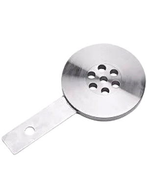
Restriction Orifice Plate
Restriction Orifice Plates can be used in either of the following
applications
- To produce a specified reduction in line pressure
- To use the restriction to create critical flow, which gives a controlled flow rate regardless of changes in downstream conditions
Multi-hole plates or multistage designs (dump systems) are often required for high pressure drop applications and to control noise levels on site.
Materials All stainless steels including Duplex, Super Duplex and 6 Mo Monel, Hastelloy B & C, Inconel, Titanium, Bronze. Other materials may be available on request.
Sizing Calculations can be supplied for bore size, thickness, noise – for single plate as well as multi hole or multi stage.
Manufacture Plates are available to suit line sizes up to 1,200 mm, in a range of thicknesses to suit the pressure drop.
Multistage/Dump systems can be supplied in most materials on request.
Integral Orifice Plate Assembly
ASVIN provides economical flow measurement products based on
differential pressure principle suitable for the line size of below 2-inch
Integral orifice assembly is a specially designed prefabricated meter
used when a high accuracy in flow measurement is required for
extremely small flow rates.
Bodies with socket-weld or threaded end connections are available.

Flow Nozzles
The Flow nozzle is a hybrid having a convergent section similar to the ISA 1932 nozzle and a divergent section similar to a venturi tube.
The flow nozzle is recommended for high accuracy..
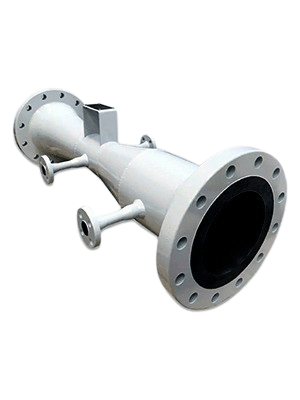
Flow Venturi
In the venturi meter the steam is accelerated through a converging
cone of angle 15-20 deg and the pressure difference between the
upstream side of the cone and the throat is measured and provides the
signal for the rate of flow.
High pressure and energy recovery makes
the venturi meter suitable where only small pressure heads are
available.

Pitot Tube
A pitot tube consists of two hollow tubes that measure pressure at
various places within the pipe. One tube gauge the impact or
stagnation pressure, and the other tube measures only the static
pressure, usually at the pipe wall. These hollow tubes can be mounted
separately in a pipe or installed together in one casing as a single
device.
The pitot meter comprises a tube that is directed towards the flow.
The fluid penetrates through the impact hole, and apart from this,
there can be two more holes in the pitot tube that act as static
pressure sources. Another pressure sensing component should be
installed on the meter to measure the static pressure. The tube axis
measuring the static pressure should be free from burrs so that the
boundary is smooth, and it should be perpendicular to the boundary.
A pitot tube is a cylinder with one end open and the other end closed.
The fluid streaming through the pipeline enters the pitot tube and
rests there. Another section within the pitot tube is filled with fluid
with static pressure. A diaphragm separates both chambers.
The measure of dynamic pressure is given by the difference in level
between the liquid in the tube and the free surface. Measuring the
impact and static pressure connected to the proper differential
pressure meter determines the flow velocity and thus the flow rate.
The flow rate is computed from the square root of the pressure. In
estimating the flow rate from the pressure, the calculation is
dependent on factors such as the location of the static tap and the
tube design. The Pitot-static probe includes the static holes in the tube
system to eradicate this parameter.
Pitot Tube Advantages
- Pitot Tube is portable and does not contain any moving parts
- It is economical
- Permanent pressure loss is low
- Pitot tube can be easily installed on an existing system
- Foreign materials in a fluid can easily obstruct the pitot tube and disrupt normal reading.
- Less accurate
- Low range
- The pitot tube is used in utility streams.
- It is used in the air duct and pipe system.
- It is used in aircraft to measure airflow velocity.
- They are used for mapping flow profiles in a channel or duct.
Rotometers - Variable Area

The rotameter is an industrial flowmeter used to measure the flowrate
of liquids and gases. The rotameter consists of a tube and float. The
float response to flowrate changes is linear, and a 10-to-1 flow range
or turndown is standard. The rotameter is popular because it has a
linear scale, a relatively long measurement range, and low pressure
drop. It is simple to install and maintain.
The rotameter's operation is based on the variable area principle: fluid
flow raises a float in a tapered tube, increasing the area for passage of
the fluid. The greater the flow, the higher the float is raised. The
height of the float is directly proportional to the flowrate. With
liquids, the float is raised by a combination of the buoyancy of the
liquid and the velocity head of the fluid. With gases, buoyancy is
negligible, and the float responds to the velocity head alone.
The float moves up or down in the tube in proportion to the fluid
flowrate and the annular area between the float and the tube wall.
The float reaches a stable position in the tube when the upward force
exerted by the flowing fluid equals the downward gravitational force
exerted by the weight of the float. A change in flowrate upsets this
balance of forces. The float then moves up or down, changing the
annular area until it again reaches a position where the forces are in
equilibrium. To satisfy the force equation, the rotameter float assumes
a distinct position for every constant flowrate. However, it is
important to note that because the float position is gravity dependent,
rotameters must be vertically oriented and mounted.
- Typically used for medium to high flow rates of liquids and
Gases.
- Available from ½” to 4” size and flow rates from 16 to 40,000 lph
(indicative water flow rate)
- Features: Borosilicate Glass tube
- End connection: Flanged or screwed
- Accuracy: +/-2% FS
- Wetted parts: CS/MS/SS/PTFE lined/Rubber lined
- Accessories: Flow switch for control
BY-PASS TYPE
ASVIN bypass Rota meter systems are designed for the accurate
measurement of fluid rate of flow in pipelines 11/2 inches in diameter
or larger. They accomplish this by providing a bypass flow that is
directly proportional to the main flow. Since Rota meters measure
bypass flow, not static differential, flow ranges up to 10 to 1 are
possible with these instruments. This provides a decided advantage
over other types of flow measuring devices.
Rota meters come in a variety of sizes and materials, but they all have
a tapered tube and a float. The "float" is the thing that rises and falls
inside the tapered tube. The float is in a continuous state of dynamic
equilibrium whose vertical position in the tube is the balance point
between the upward force of the fluid, or gas, and the downward force
of gravity on the float. The point of equilibrium is strongly affected by
specific gravity and viscosity changes. The viscosity limit for bypass
Rota meters is 3.0 centipoises.
The float material is selected to provide a certain weight, which when
used with a specific tube taper will provide the proper range. In large,
10" and 5" scale units, the most common float material is SS 316 or
Hast C. However, aluminum, PVC, PP can also be used.
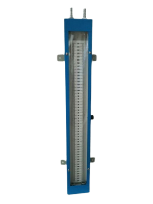
Manometers
Manometers are defined as the devices used for measuring the
pressure at a point in a fluid by balancing the column of fluid by
the same or another column of liquid.
(i) U-tube manometer, and (ii) Single column manometer.
(iii) Inclined manometer.
Simple Manometers: manometer is one which consists of a glass
tube whose one end is connected to point where pressure is to be
measured and the other end remains open to atmosphere.
Thermowells
ASVIN thermowell serves as a protective barrier between a
thermometer and the process media. Thermowells are often found
in industrial process systems within refineries and petrochemical
and chemical plants. Used as protective devices for the temperature
sensing elements machined from special quality bar-stock and
drilled with extreme accuracy to obtain uniformity of thickness.
Concentricity is held to within 5% wall thickness, depending on
length of well.
End Connections: Threaded to socket welded or flanged.
Material of construction: - Carbon steel,304, 304L, 316, 316L alloy
steel etc.
Internal Bore: 1/4" to 5/8"
IBR Quality also can be supplied.

Thermocouples
ASVIN thermocouple is a temperature measuring device that is exposed
to a process in order to determine its temperature. A thermowell is a
structure that surrounds the thermocouple (or RTD) probe and protects
it from aspects of the process such as fluid flow rates or caustic or
degrading materials.
Thermocouples are used in industrial processes, to electric power
generation, to furnace monitoring and control, to food and beverage
processing, to automotive sensors, to aircraft engines, to rockets,
satellites and spacecraft.
The conductor materials in base metal thermocouples are made of
common and inexpensive metals such as Nickel, Copper and Iron. The
Type E thermocouple has a Chromel (Nickel-10% Chromium) positive
leg and a Constantan (Nickel- 45% Copper) negative leg.

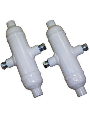
Condensing Pots
ASVIN thermocouple is a temperature measuring device that is exposed
to a process in order to determine its temperature. A thermowell is a
structure that surrounds the thermocouple (or RTD) probe and protects
it from aspects of the process such as fluid flow rates or caustic or
degrading materials.
Thermocouples are used in industrial processes, to electric power
generation, to furnace monitoring and control, to food and beverage
processing, to automotive sensors, to aircraft engines, to rockets,
satellites and spacecraft.
The conductor materials in base metal thermocouples are made of
common and inexpensive metals such as Nickel, Copper and Iron. The
Type E thermocouple has a Chromel (Nickel-10% Chromium) positive
leg and a Constantan (Nickel- 45% Copper) negative leg.
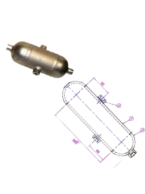
Seal-Pots
Seal pots (sometime called condensate pots) are used to allow a liquid
seal between the instrument and flowing gases such as steam. Their
function is to keep the liquid level constant in the impulse tubes. For
example, in boiler liquid level applications the high pressure (HP) side
a differential pressure transmitter is connected to the vapor space on
top of the steam drum. Steam condenses in the chamber or seal pot
and fills the impulse line with condensate. The seal pot is located to
allow the condensate to drain back to the source thus keeping the
liquid level constant.
Insulating the seal pot would inhibit its function. The seal pot, unlike
the impulse tubes, is not vulnerable to freezing during normal plant
operation because it is in constant contact with a heat source, steam.
The only time that the seal pot is vulnerable to freezing is if the plant
is shut down during freezing ambient temperatures. In this case the
seal pot would need to be drained.
Seal pots are used in the flow measurement of high-density and
corrosive media to protect differential pressure measuring instruments
from these media. The seal pots are filled with a non-mixable sealing
liquid which, due to the difference in density, forms a sealing layer
towards the medium. This sealing layer ensures that the measuring line
to which the differential measuring instrument is connected is
separated from the medium. The sealing liquid serves as a pressure
transmission medium. Seal Pots is designed to drain out foreign or
residue material from the pipeline thereby guarding critical
components of instrumentation system. Generally, Steam is passed
through Seal Pot. The condensate residue is drained from the bottom
valve connection. Installation can be either vertical or horizontal lines
depending on the system requirement. Also Seal Pots is used before
the pressure transmitters line because temperature of steam is very
high so this high temp. Steam directly may damage diaphragm of the
pressure transmitter.
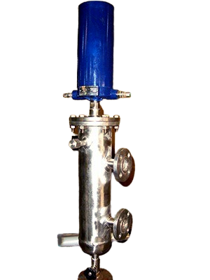
Constant Head Chambers
A constant head Chamber/ reservoir is required to maintain a
consistent head in the reference leg of the transmitter. This is often
referred to as a” wet leg” The output of the electronic DP transmitter
is the process Input for the Controller, and the output is then
compared to a drum level set-point. Any discrepancy between set-
point and drum level causes an output from the controller in
compensation. The constant condensation in the top connection
maintains a constant influx of hot water at equilibrium with the steam.
This maintains the heat and ensures both wet leg and measurement
sections are at the same temperature (that of the water in the steam
drum), below the apparatus, the two impulse lines are in close contact
and therefore at the same temperature. Whatever the density of the
water is, it is the same in both legs and cancels out in the differential
measurement.

Level Switches
As level of a liquid in a vessel rises, the float rides on the liquid
surface moving the magnetic sleeve upward in the enclosing tube
and into the field of the switch mechanism magnet. As a result, the
magnet is drawn in tightly to the enclosing tube causing the set
screw to actuate the switch arm, making or breaking the electrical
circuit. As the liquid level recedes, the float and magnetic sleeve
move downward until the switch
magnet releases and is drawn outward, away from the enclosing
tube by a tension spring. This in turn causes the set screw to move
the switch actuating arm in the opposite direction, thus reversing
switch action. Switch mechanisms may include a single switch or
multiple switches, depending on operational requirements and
switching action desired.
Application- Feedwater heater high and low alarm, Primary steam
drip pot, Refinery applications
Paper processing H2S atmosphere, Offshore salt atmosphere,
Chemical plant corrosive atmosphere, High temperature reactors,
high and low alarm
INTERNAL SIDE MOUNTED FLOAT- SIDE CHAMBER
ASVIN magnetic horizontal float switches (“float switches”) are ideal
for high and low liquid level alarm, and pump control duties. The float
switch is designed to open or close a circuit (“switch”) as a changing
liquid level within a vessel passes the level of the float (the Switch
Point). When the process liquid level is below the Switch Point,
contacts B-B are made (together) and contacts A-A are open. When the
process liquid level is above the Switch Point, contacts A-A are made
(together) and contacts B-B are open.
Special features- Magnetically coupled, No glands or linkages that
could cause leaks, No springs means reduced maintenance, Snap action
switching, No contact hover or bounce for clean make or break,
Hermetically sealed switch mechanism is available to eliminate
freezing and corrosion of contacts and all moving parts
EXTERNAL CHAMBER
Float Chambers - manufactured in approved materials: -
Cast iron equal to BS. 1452 Grade 17 for up to 13kg/cm2 rating.
Fabricated steel BS.3602 - HFS 27 for both 21kg/cm2 and 32kg/cm2
ratings. For chamber dimensions
Switch head - containing one or more switch units mounted in a
housing comprising a die-cast base
with a zinc coated mild steel casing. Two 25mm BS.4568 cable entries
are provided.
Switch units - have single pole double throw contacts, are latching and
are positioned and held in place by clamp screws.
Centre tube - made of non-magnetic stainless steel and expanded into
the top cover flange, it is fitted with a stop cap which also acts as a
guide for the float rod carrying the primary magnet. Float -
manufactured in Monel metal.
Float rod - manufactured in stainless steel.
Our Products
- Safety Valve
- Relief Valve
- Safety Relief Valve
- Thermal Relief Valve
- Conventional Safety Relief Valve
- Balanced Safety Relief Valve
- Balanced Bellows Safety Valve
- Sentinal Relief Valves
- Pilot Operated Safety Relief Valves
- Rupture Disc
- Tubular Level Indicator
- Reflex Level Indicators
- Transparent Level Indicators
- Magnetic Level Indicators
- Bi-Colour Level Indicators
- Remote IGEMA Level Indicators
- Fullview Glasses
- Ball Flow Indicators
- Double Window Plain
- Double Window Drip
- Double Window Flapper
- Double Window Rotating Wheel
- OPA - Orifice Plate Assemblies
- Restriction Orifice Plate
- Integral Orifice Plate Assembly
- Flow Nozzles
- Flow Venturi
- Pitot Tube
- T Type Strainers
- Y Type Strainers
- Basket Strainers
- Duplex Strainers
- Conical / Temporary Strainers
- Magnetic Strainers
 ASVIN
ASVIN